Kalkulator ubytku powietrza
Kalkulator ubytku powietrza stosowany jest jako narzędzie do szybkiego obliczania równoważnej przewodności cieplnej małych ubytków powietrza i szczelin powietrznych w oparciu o wejście ich wymiarów i kierunku strumienia ciepła.
Aby obliczyć równoważne przewodności ciepła (lambda) Aplikacja używa formuły definiujące obliczania oporu przenikania ciepła przestrzeni powietrznych opisanych w EN ISO 6946: 2005, załącznik B - należy zdawać sobie sprawę z ograniczeń związanych z jego stosowaniem (np małe, zamknięte ubytki powietrza). Regulacja obliczenia są nastawione do norm europejskich EN ISO 6946 i EN ISO 10077-2 i obejmują dwa obliczenia wymiarów.
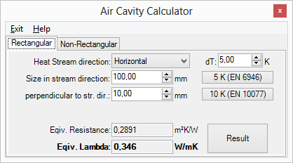
Kierunek strumienia ciepła: Określenie kierunku strumienia ciepła:
- Poziomo domyślnie)
- Ku górze
- Ku dołowi
Thickness (stream dir.): The thickness of the cavity measured in the heat stream direction.
Remark: Thickness and width can be swapped via a context menu.
Width: The width of the cavity (perpendicular to the thickness)
Remark: Thickness and width can be swapped via a context menu.
Temperature difference dT: The difference of temperature between cavity boundaries in the heat stream direction.
Equiv. Resistance: Equivalent heat transfer resistance of particular air cavity
Equiv. Lambda: Equivalent heat conductivity of particular air cavity
Result: Calculation result is replaced by the actual value.
Remark: According to normative regulations one shall set the temperature difference, if exact value is not known, accordingly. Buttons "5K (EN 6946)" and "10K (EN 10077) set this value to one of magnitudes required in these respective regulations.
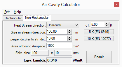
For the very usual case of non rectangular air cavities normative regulations define following procedure to account for:
An equivalent conductivity is to be calculated for a fictive rectangular cavity. Such fictive cavity shall be constructed as follows:
- create a rectangle surrounding the cavity of interest.
- the area of a fictive cavity rectangle shall be equal to the area original (non rectangular) cavity.
- the ratio of width to the height of the fictive rectangle cavity shall be the same as of the rectangle surrounding the original.
The conductivity calculated for such fictive rectangular cavity is the used instead for the (non rectangular) original air cavity.
Heat Stream direction: Definition of heat stream direction:
- Horizontal (default)
- Upwarads
- Downwards
Thickness (stream dir.): The thickness of the cavity measured in the heat stream direction.
Remark: Thickness and width can be swapped via a context menu.
Width: The width of the cavity (perpendicular to the thickness)
Area: The actual are of the real (non rectangular) air cavity
Remark: Thickness and width can be swapped via a context menu.
Temperature difference dT: The difference of temperature between cavity boundaries in the heat stream direction.
Equiv. Resistance: Equivalent heat transfer resistance of particular air cavity
Equiv. Lambda: Equivalent heat conductivity of particular air cavity
Result: Calculation result is replaced by the actual value.